This post is an illustrated guide / tutorial to setup CR403S Codesys 3.5 projects with service (debug) communication. It can be used by beginners in both Codesys 3.5 as well as a reference guide to professionals needing to spin up a quick prototype.
At the end of the tutorial, we will run and monitor the code to toggle an I/O to, for instance, blink an LED.
The hardware
For this tutorial, we will be using the IFM CR403S PLC, an IFM EC2112 CAN Interface (CANFox), and a separate CAN logger to check the data sent on the CAN bus.
The software
Codesys 3.5 SP18
Codesys GmbH, formerly known as 3S GmbH, integrates two very different pieces of software: the Codesys runtime, and the Codesys IDE.
When building and releasing PLCs, manufacturers will validate their device with a version of a runtime. It is linked to a version of the IDE (development environment) providing the Codesys-validated libraries for this runtime. Hence the need of precisely installing Codesys 3.5 SP18. So at https://store.codesys.com/en/codesys.html make sure you download the right version. If the install seems to hang, it typically will get unstuck at some point, be patient.
Drivers and documentation
IFM makes publicly available install and documentation packages for their tools and PLCs:
For the CR403S: https://www.ifm.com/nl/en/product/CR403S#documents
For the EC2112: https://www.ifm.com/nl/en/product/EC2112#documents
Make sure you follow the install instructions in order.
Code the Blinking LED
Create Codesy-IFM project
In File/New Project, select an ifm ecomatBasic project: it should be available if you have followed the installation steps correctly. I will call this project J1939_Tutorial.

Find the IFM CAN Service port in Codesys
Next step is to make sure that your PLC is found by the Codesys CAN Gateway.
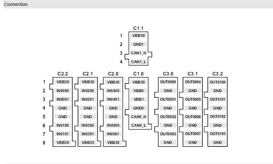
Connect the IFM CAN adapter to the CAN 0 of the IFM controller at C1.0:
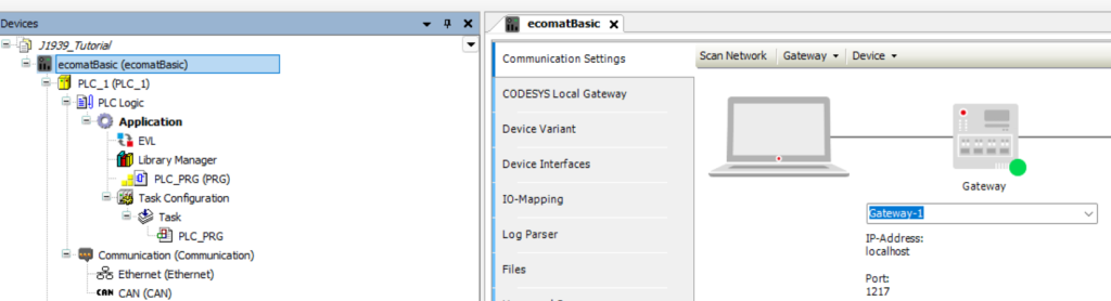
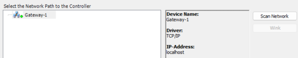
Double-click on the device you want to connect to to open its settings page, and start a “Scan Network”.
It probably failed at this stage to find the controller.
Go to the Codesys Local Gateway tab at the left, and an example parameter is given below:

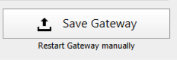
Click on Save Gateway at the bottom right of the configuration.
Find the Codesys Gateway Icon in the windows quick access icon lists
Left-click, stop the gateway, wait a couple of seconds, and start the gateway again.
This is a fiddly part in case you have different tools. Make sure only the IFM CAN adapter is connected to your computer (no IXXAT or ethernet connection to another PLC) to find the CR403S device. Restart the gateway and save configuration mutiple times if needed. If it succeeds Codesys typically finds the device right away.

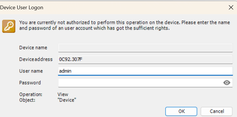
Double-click on the root device, and enter “admin” with no password as the default login information.
Creating the Application
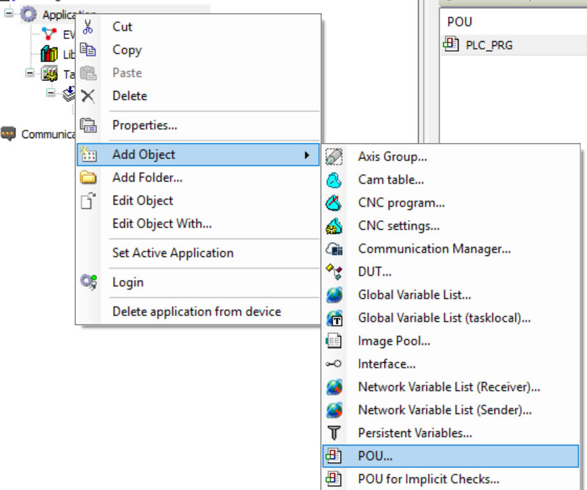
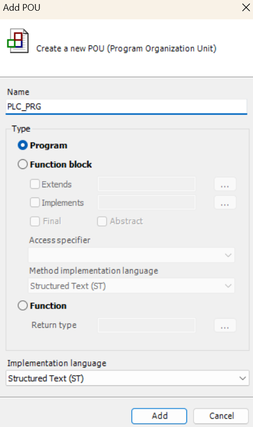
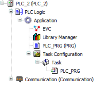
Codesys relies on an entry point, a POU named “PLC_PRG (¨PRG)”. This POU is called by the Task with the same name (you can also configure the task by double-clicking on “Task”). There is no need for the POY to be of a particular type, and as I am more used to coding, we will replace the existing “PLC_PRG (PRG)” of PLC_2 with an ST formatted PLC_PRG (PRG).


Coding the I/O Toggle
Add Libraries
Two libraries are needed, the standard library with Codesys standard functions and function blocks (such as the TON function block), and the IFM IO library
Double click on library manager in the left panel
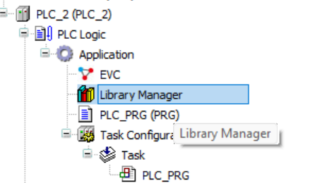
Click on Add Library
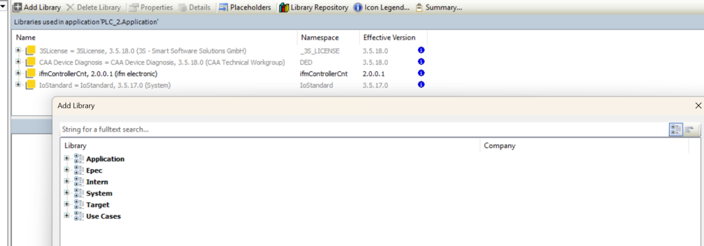
Look for the name of the library ( ifmIOCommon ) and add it.

Alternatively, you can look for the name of a function or function block, such as looking for TON to find the standard library. Add the standard library as well.

Code the Application
No additional configuration is needed to toggle I/Os and read simple outputs. There are more details in the IFM document programming_manual_CR403S, section ifm Function Libraries (I am not linking to it as I expect IFM to have the more up to date version on their site).
We are coding the application on PLC_2, and we will toggle output OUT0000 (group 0, channel 0) on connector C3.0.
In the variable header:
PROGRAM PLC_PRG
VAR
	// Standard lib timer function block
	fbTimer : TON;

	// ifm library output function block
	fbOut0000 : ifmIOcommon.Output;
END_VAR

In the main body:
// Run the timer FB every loop to check for time elapsed
fbTimer(IN:= TRUE, PT:= T#1S);
// (Called each time, but can be set only once)
fbOut0000.uiChannel := 0;
IF fbTimer.Q THEN
// Restart the timer
fbTimer(IN:=FALSE);
// If the output status is 1, then turn off the LED,
// if it is 0, then turn it on.
IF fbOut0000.xOutState THEN
fbOut0000( uiValue := 0 );
ELSE
fbOut0000( uiValue := 1 );
END_IF
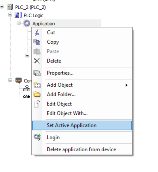
END_IFBuild the project (F11) and set the second application as active.
Log In and Monitor
Log in to the PLC and replace / download the application fully if asked.

Click on start, as at the moment the PLC is stopped.

The values should change live

Troubleshooting:
- Do not short the output, as the value is measured by the PLC to detect if it is ON or OFF.
- Make sure you call the Output function block every loop. Setting uiValue as in fbOut0000.uiValue := 1; is not enough, a call occurs with parenthesis fbOut0000( uiValue := 1) ;
- In case the device is not connected, go back the the paragraph about connecting with the Codesys Gateway.
Conclusion
Setting up projects is not something that we do all the time, and it is easy to forget a step (why can’t my project find standard functions? where should I code?…), having a reference sheet with illustrations make it easy to remember the actions.
With this illustrated, non-YouTube tutorial, the hope is that it can be used as references to troubleshoot a project or for newcomers to learn to do it themselves.
Feel free to contact me for any request regarding PLC software development or for copies of the project.